
A 5G modem and a precision analogue sensor sharing a PCB are not unusual designs today. It is a standard one. And without adequate shielding, the modem’s switching transients corrupt the sensor’s measurement before the signal ever reaches the processor.
Electromagnetic interference (EMI) and radio frequency interference (RFI) are not edge-case concerns for specialist applications. They are routine design constraints in any assembly where high-frequency switching, RF transmission, and sensitive analogue or digital circuitry occupy the same physical space. As device density increases, operating frequencies climb, and form factors shrink, the interference environment inside modern electronics grows more severe with each product generation.
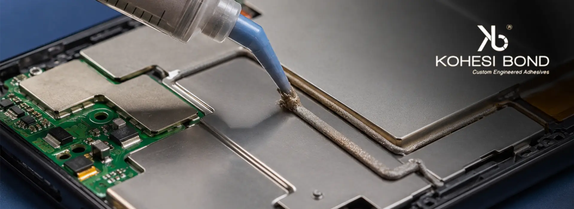
EMI shielding adhesives address this by creating continuous conductive barriers that contain emissions and block incoming interference, while simultaneously bonding shield structures to housings and ground planes. At Kohesi Bond, we engineer conductive epoxy bonding adhesive systems for EMI/RFI control where shielding effectiveness, bond integrity, and process compatibility are all treated as primary design requirements.
Table of Contents
ToggleA] Understanding EMI and RFI in Electronic Systems
1. What Causes EMI and RFI
Interference originates from both internal and external sources. Internally, switching power converters generate broadband conducted and radiated noise across frequencies from tens of kHz to hundreds of MHz. RF transmitters in wireless modules radiate intentionally at defined frequencies but produce harmonics that couple into adjacent circuitry unintentionally.
Clock signals and fast digital edges generate spectral content well beyond their fundamental frequency, radiating from PCB traces that act as inadvertent antennas.
External sources include cellular and Wi-Fi infrastructure, industrial equipment, automotive ignition systems, and adjacent electronic assemblies within the same product enclosure. In dense multi-board systems, one module’s emissions become another module’s susceptibility problem.
2. Impact on Electronic Performance
Uncontrolled electromagnetic interference shielding failures manifest as signal distortion in analogue measurement circuits, bit errors in high-speed digital links, spurious triggering in microcontroller peripherals, and noise floors that degrade RF receiver sensitivity.
Beyond functional degradation, uncontrolled emissions create regulatory compliance failures under FCC Part 15, CE marking requirements, and CISPR standards, with re-testing costs and product launch delays that dwarf the cost of adequate shielding at the design stage.
3. Why Shielding is Necessary
A conductive enclosure around an interference source or sensitive receiver attenuates electromagnetic fields through reflection and absorption. Shielding effectiveness (SE) is measured in decibels and quantifies the ratio of field strength with and without the shield in place. Achieving 40-60 dB SE across the frequency range of concern is a typical requirement in consumer and industrial electronics; medical and aerospace applications routinely demand 80 dB or above.
B] Traditional EMI/RFI Shielding Methods and Their Limitations
1. Metal Enclosures and Shielding Cans
Stamped metal shielding cans soldered or mechanically fastened to PCBs provide reliable broadband shielding but impose constraints that modern compact assemblies increasingly cannot accommodate. Mechanical fasteners require clearance zones that consume board area. Press-fit cans rely on continuous contact between the can perimeter and a soldered fence and any gap in that contact from board warpage, solder voids, or dimensional tolerance stack-up. This creates a slot antenna that radiates at frequencies where the slot length approaches a half-wavelength.
2. Conductive Gaskets and Foils
Conductive elastomeric gaskets provide compliant contact across seam interfaces but require compressive clamping force to maintain conductivity. In lightweight or thin-wall enclosures without adequate structural stiffness, that clamping force is unavailable. Foil tapes provide quick application but degrade at elevated temperatures, lose adhesion after thermal cycling, and create assembly complexity in automated production environments where peel-and-stick processes are difficult to control at the tolerances shielding continuity demands.
3. Soldered Shielding Solutions
Soldering shield cans directly to PCB ground fences provides excellent initial conductivity but restricts rework access and imposes reflow temperatures on any components beneath or adjacent to the shield. This creates rigid mechanical connections that concentrate thermal stress at solder joints during temperature cycling. In assemblies where component access for firmware updates or repair is a product requirement, a soldered shield can become a significant serviceability liability.
C] Role of Conductive Adhesives in EMI/RFI Shielding
1. Electrical Continuity and Grounding
EMI shielding solutions using conductive adhesives create continuous, low-resistance conductive paths between shield structures and ground planes across the full bond perimeter. Unlike mechanical fasteners that provide point contacts, or gaskets that require compression to conduct, an adhesive bond establishes intimate conductive contact across its entire interface area. Surface resistivity of cured silver-filled systems in the range of 0.001-0.01 Ω/sq provides the low-impedance ground connection that effective shielding requires across frequencies from MHz to GHz.
2. Combined Bonding and Shielding Function
A conductive adhesive joint bonds the shield mechanically and grounds it electrically in a single process step. This eliminates the separate mechanical fastening and gasketing steps that traditional methods require, reducing component count, assembly time, and the number of process variables that must be controlled to achieve consistent shielding performance. In a production line running thousands of units per day, eliminating two assembly steps per unit is a measurable cost reduction.
3. Design Flexibility
Radio frequency interference shielding requirements in modern compact assemblies frequently involve curved surfaces, irregular geometries, and mixed-material interfaces where rigid metal solutions cannot conform. Conductive adhesives in paste or film form conform to complex surface geometries and bond dissimilar materials, including metals, ceramics, and polymers, in a single application. They can also be dispensed with automated equipment at the tolerances that fine-pitch shielding designs require.
Need reliable EMI/RFI shielding for sensitive electronics?
Choose Kohesi Bond conductive adhesives for dependable electromagnetic protection.
D] Types of Conductive Adhesives Used for EMI/RFI Shielding
1. Silver-Filled Conductive Adhesives
Silver-filled epoxy systems deliver the lowest surface and volume resistivity available in adhesive form, with bulk resistivity in the range of 1×10⁻⁴ to 5×10⁻⁴ Ω·cm. For applications requiring SE above 60 dB, or where shielding must be maintained after thermal cycling and humidity exposure, silver-filled systems are the correct baseline specification. Silver oxide’s inherent conductivity prevents the resistance creep that affects other filler systems over service life, making silver the reliable choice for long-life or harsh-environment shielding applications.
2. Nickel-Filled Conductive Adhesives
Nickel-filled systems offer SE in the 40-60 dB range at significantly lower material cost than silver-filled alternatives. Bulk resistivity typically runs 1×10⁻² to 1×10⁻¹ Ω·cm, adequate for general-purpose RFI shielding and grounding applications where absolute conductivity is less critical than cost per unit area covered. The limitation is nickel oxide formation under sustained humidity exposure, which drives resistance upward over service life in demanding environments. For benign indoor environments and moderate SE requirements, nickel-filled systems provide acceptable performance at lower cost.
3. Carbon-Based Conductive Adhesives
Carbon black and graphite-filled adhesive systems are used where ESD control and low-level shielding are the requirements rather than high SE. Surface resistivity in the range of 10² to 10⁴ Ω/sq provides ESD dissipation and partial shielding at the lowest material cost and with the best mechanical compliance of any filled system. For flexible or lightweight enclosures where silver or nickel loading would add unacceptable mass or stiffness, carbon-based systems offer a practical alternative.
4. Hybrid Conductive Systems
Hybrid formulations combining silver with carbon or nickel fillers balance conductivity, flexibility, and cost for applications where no single filler type satisfies all requirements simultaneously. A silver-nickel hybrid, for instance, provides resistivity intermediate between pure silver and pure nickel systems while partially mitigating nickel oxidation through the presence of silver at particle contact interfaces. These systems are selected when the SE requirement, cost constraint, and environmental exposure conditions together rule out both pure silver and pure nickel alternatives.
E] Key Performance Factors in EMI/RFI Shielding Applications
1. Electrical Conductivity and Shielding Effectiveness
Shielding effectiveness scales with the conductivity of the shield material but does not increase linearly with it. The relationship for a conductive layer of thickness t and conductivity σ follows:
SE (dB) = 20 log₁₀ (1 + Z₀σt / 2)
Where:
- SE = shielding effectiveness in decibels
- Z₀ = impedance of free space (377 Ω)
- σ = electrical conductivity of the shielding material (S/m)
- t = thickness of the conductive layer (m)
This equation shows that SE increases with both conductivity and layer thickness, but with diminishing returns at high conductivity values. Doubling conductivity does not double SE; the logarithmic relationship means that meaningful SE gains above 60 dB require attention to shield geometry and seam continuity as much as to material conductivity.
2. Adhesion and Mechanical Integrity
A shielding adhesive that loses bond integrity under vibration or thermal cycling creates intermittent ground connections that are worse than no shielding at all: the partially bonded shield resonates at mechanical frequencies and radiates more effectively than an open aperture. Lap shear strength after 1000 thermal cycles and after 500 hours at 85°C/85% RH must both be specified and validated, not inferred from as-cured data.
3. Environmental Resistance
EMI/RFI shielding materials in automotive underhood locations, outdoor IoT enclosures, and industrial equipment face sustained humidity, temperature extremes, and chemical exposure. Conductivity retention after environmental ageing is the relevant specification, not initial conductivity. A silver-filled system that retains bulk resistivity within 2x of its as-cured value after 1000 hours at 85°C/85% RH is a qualified material. One that drifts 10x under the same conditions is not, regardless of its initial datasheet value.
4. Processing and Cure Compatibility
Automated dispensing compatibility requires viscosity and thixotropy matched to the dispensing method: screen printing for large-area shield coatings and jet or needle dispensing for precision bond lines on shield can perimeters. Cure temperature must be compatible with any temperature-sensitive components already assembled on the board. One-part heat-cure systems offer indefinite ambient pot life for high-volume automated lines; two-part systems provide flexibility for lower-volume applications where oven cure is impractical.
F] How Kohesi Bond Supports EMI/RFI Shielding Design
1. Material Selection Guidance
The correct EMI shielding adhesive depends on the SE requirement, operating environment, substrate materials, and production process constraints working together. Kohesi Bond’s selection process starts with the frequency range and SE target, establishes the conductivity requirement from the SE equation, then narrows to the filler system and matrix chemistry that satisfies adhesion, environmental resistance, and process compatibility simultaneously.
2. Custom Formulation Capability
As a leading adhesive manufacturing company in India, Kohesi Bond leverages extensive technical expertise to engineer custom systems with targeted surface resistivity, viscosity, cure temperature, and flexibility. Custom formulations are validated against application-specific shielding effectiveness tests, not just bulk resistivity measurements, because SE is a system property that depends on shield geometry and contact quality as well as material conductivity.
3. Application and Qualification Support
Kohesi Bond provides dispensing parameter guidance, cure profile recommendations, and shielding effectiveness test support to move engineering teams from material selection to qualified production processes. For automotive and aerospace applications, full documentation, including TDS, SDS, and CoC, accompanies every order, supporting IATF 16949 and AS9100 quality management system requirements.
Conclusion
EMI and RFI are not solved by shielding material alone. They are solved by conductive continuity across every bond interface, every seam, and every ground connection in the shield structure. A gap of 1 mm in a shield perimeter bond line at 3 GHz is a slot antenna, not a minor assembly defect.
Conductive adhesives address the continuity requirement that mechanical fasteners and gaskets cannot consistently deliver, while simultaneously simplifying assembly, enabling complex geometries, and reducing process steps. Kohesi Bond’s EMI shielding solutions are engineered for the full combination of electrical, mechanical, and environmental demands that production shielding applications impose. Contact our applications team to discuss your specific frequency range, SE target, and assembly constraints.
Enhance signal integrity with advanced shielding solutions.
Trust Kohesi Bond conductive adhesives for durable EMI/RFI protection.
FAQs
Silver-filled epoxy systems are the specification baseline for applications requiring SE above 60 dB or long-term conductivity stability in humid or thermally cycled environments. Nickel-filled systems are adequate for moderate SE requirements in benign environments at lower cost. The correct choice is determined by the SE target, operating environment, and service life requirement, not by material cost alone.
Start with the SE requirement and frequency range, which together define the minimum conductivity the adhesive must deliver. Then establish the maximum cure temperature the assembly can tolerate, the substrate materials the adhesive must bond, and the environmental exposure conditions it must survive. Resistivity after ageing, not as-cured resistivity, is the specification that determines whether the material will still be shielding effectively at the end of its service life.
Yes, and in several respects a superior one. Adhesive bonds provide continuous conductive contact across the full shield perimeter rather than point contacts at solder joints, eliminating the gap-induced slot antenna effect. They also protect heat-sensitive components from reflow temperatures, enable rework access, and survive thermal cycling without the fatigue cracking that solder joints develop at shield can perimeters over time.
Automotive electronics, where shielding cans in ECUs and sensor modules must survive vibration and thermal cycling; medical devices, where regulatory emissions limits and patient safety requirements demand reliable, reworkable shielding; aerospace and defence, where SE requirements above 80 dB combine with weight constraints that favour adhesive over mechanical solutions; and consumer electronics, where production volume and assembly automation make adhesive dispensing more practical than soldering or gasketing.
Filler type is the primary driver: silver-filled systems cost significantly more per unit weight than nickel- or carbon-filled alternatives but cover less area per gram given their higher-density filler loading. Total cost of ownership should account for assembly steps eliminated, rework access preserved, and field failure rates reduced, not just material cost per gram.

Utsav Shah is a 34-year-old entrepreneur with a passion for scientific discovery. Utsav’s journey began with a deep dive into materials science, earning degrees from USC and the Institute of Chemical Technology. He’s the visionary founder of Kohesi Bond, a top-rated adhesive manufacturer, and Cenerge Engineering Solutions, a leader in heat exchangers and cryogenic pumps. With over a decade of experience, Utsav consults across various industries, ensuring they have the perfect adhesive solution for their needs. Connect with him on LinkedIn!